Pipe Pressure Testing: Methods and Standards Guide
Pipe pressure testing is the process of verifying that a pipeline can safely contain its design pressure without leaking, rupturing, or deforming beyond acceptable limits. The most common methods are hydrostatic testing with water, pneumatic testing with compressed air or gas, leak testing at lower pressures, and vacuum testing for gravity systems.
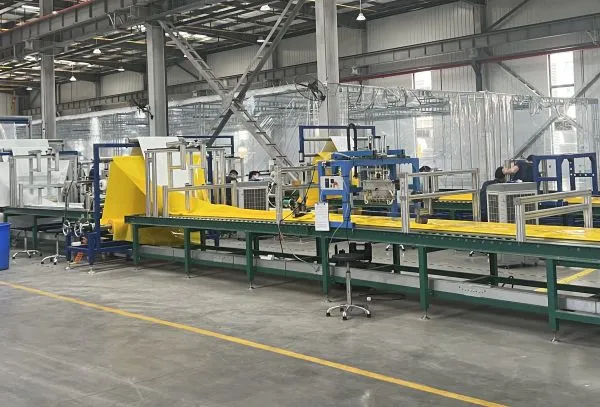
Every pipeline that carries water, sewage, chemicals, or industrial fluids must prove its integrity before it goes into service. A failed pressure test can delay project handover by weeks, trigger costly repairs, and damage a contractor's reputation. At Qingdao Yongke Machinery, we have manufactured pipe production and rehabilitation equipment for clients in more than thirty countries since 2010. We understand that pressure testing is the final gate between installation and operation. This guide explains the pipe pressure testing methods, standards, and best practices that municipal and industrial project teams use to certify pipeline integrity.
Key Takeaways
Hydrostatic testing is the safest and most widely accepted pipe pressure testing method, using water at 1.25 to 1.5 times the design pressure for a defined hold period.
Pneumatic testing is faster and uses compressed air or nitrogen, but it requires stricter safety controls because compressed gas stores more energy than water.
Leak testing, vacuum testing, and initial service tests are lower-pressure alternatives used for gravity sewers, drainage systems, and sensitive installations.
Pre-test preparation includes inspecting joints, cleaning the line, installing calibrated gauges, and isolating equipment that cannot withstand the test pressure.
Common acceptance standards include AWWA C605, ASTM F2164, EN 805, ISO 1167, and project-specific specifications; always confirm the governing code before testing.
What Is Pipe Pressure Testing?
Pipe pressure testing confirms that a completed pipeline, vessel, or piping system can withstand its required operating pressure. The test subjects the pipe to a pressure higher than normal operating conditions for a controlled period. Inspectors then check for leaks, visible deformation, pressure loss, or other signs of failure.
Pressure testing serves three main purposes:
Verify structural integrity: Confirms that pipe, fittings, and joints can handle design pressure plus a safety margin.
Detect leaks: Identifies defective joints, cracks, or damaged sections before the line enters service.
Demonstrate compliance: Provides documentation that the installation meets contract specifications and regulatory requirements.
The test medium, pressure multiplier, hold time, and acceptance criteria all depend on the pipe material, diameter, application, and applicable standard. A water distribution line, a sewer force main, an industrial chemical line, and a gas pipeline each require different testing protocols.
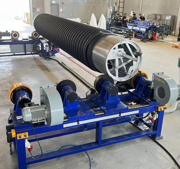
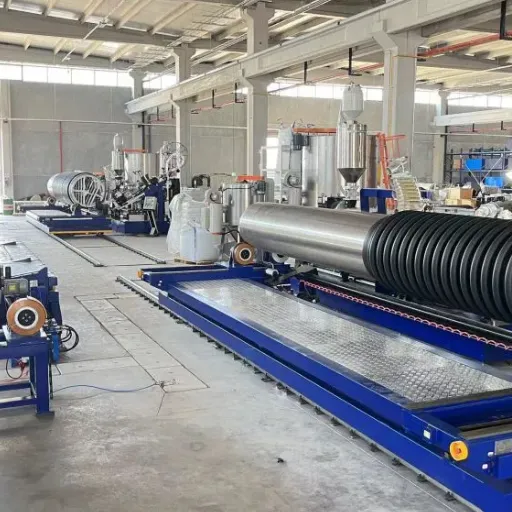
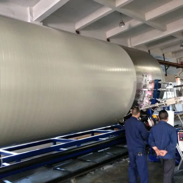
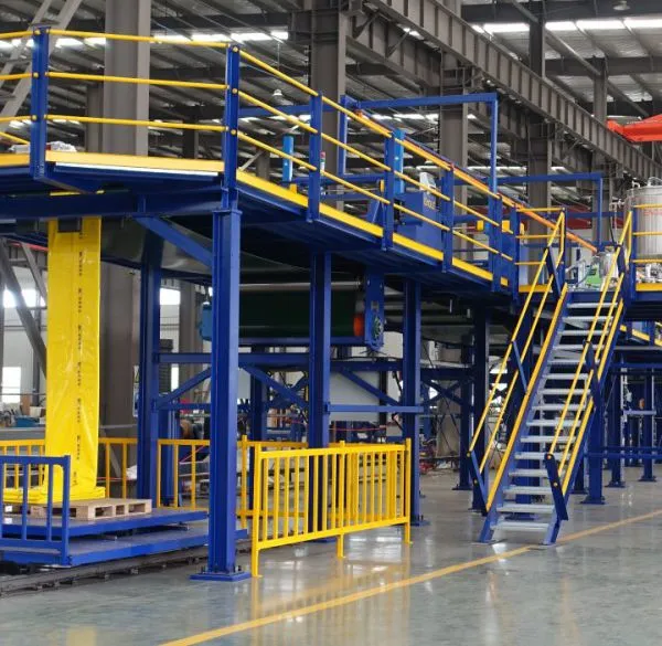
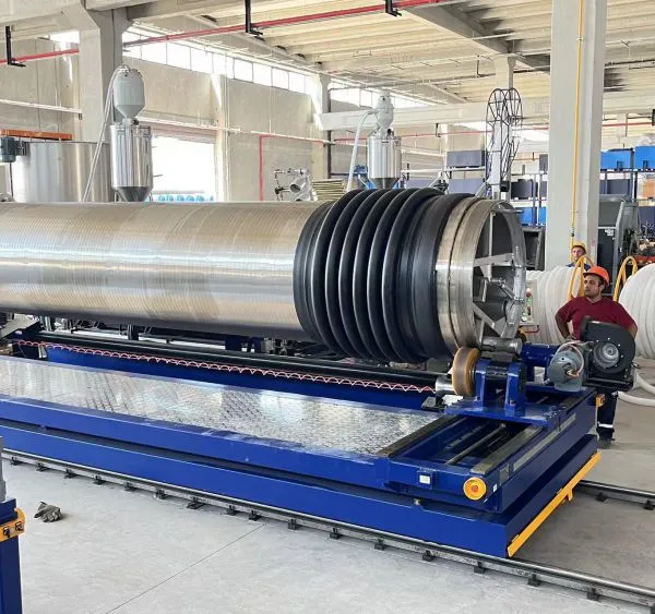
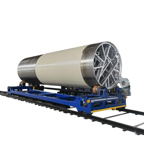
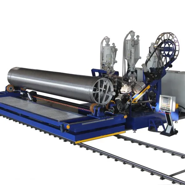
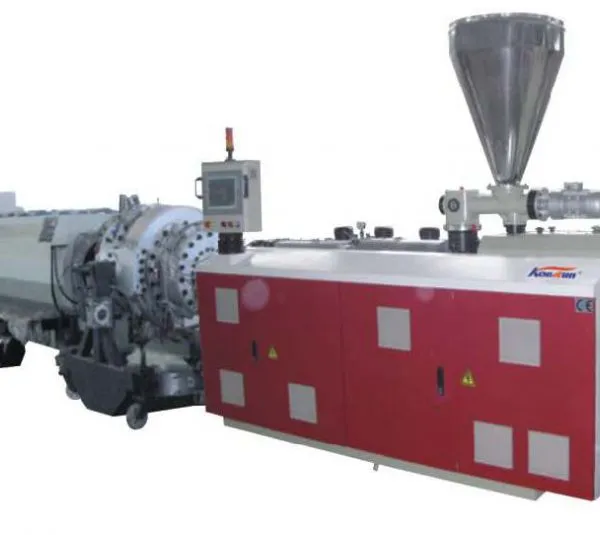
Need consistent pipe quality to pass pressure tests the first time? Our HDPE spiral profile pipe machine produces pipes from DN300mm to DN5000mm with controlled wall thickness and structural integrity for municipal and industrial applications.
Common Pipe Pressure Testing Methods
Hydrostatic Pressure Testing
Hydrostatic testing uses water as the test medium. It is the preferred method for most municipal and industrial pipelines because water is nearly incompressible. If a failure occurs, the stored energy releases much more slowly than with compressed gas, reducing the hazard to workers and surrounding property.
A typical hydrostatic test procedure includes:
Fill the line slowly: Remove air pockets through vents and taps; trapped air causes pressure spikes and false readings.
Pressurize to test pressure: Usually 1.25 to 1.5 times the design pressure, depending on the standard.
Hold the pressure: Maintain the test pressure for a specified duration, commonly 1 hour for small diameters and up to 24 hours for large pipelines.
Monitor for pressure loss: Acceptable leakage is typically expressed as a maximum pressure drop or allowable make-up water volume over the hold period.
Inspect joints and fittings: Walk the line and check for visible leaks, sweating, or movement.
Hydrostatic testing is standard for water mains, force mains, fire protection lines, and many industrial process lines. It is required by AWWA C605 for water distribution systems and by ASTM F2164 for HDPE pressure pipe.
Pneumatic Pipe Testing
Pneumatic testing uses compressed air, nitrogen, or another inert gas. It is faster than hydrostatic testing because the line does not need to be filled with water and later drained. It is also useful in cold climates where water freezing is a concern.
However, pneumatic testing carries higher risk. Compressed gas stores significant potential energy. A rupture can propel pipe fragments and create a shock wave. For this reason, standards place strict limits on pneumatic test pressure and require:
Reduced test pressure, often 1.1 times design pressure rather than 1.5
Barriers and restricted access zones during testing
Pre-test inspection of pipe and joints for visible defects
Gradual pressurization in stages to allow observation
Pneumatic testing is common for gas pipelines, compressed air systems, and lines where moisture cannot be tolerated.
Leak Testing and Initial Service Tests
Leak testing applies a relatively low pressure, often just above operating pressure, to verify joint tightness. It is used when a full hydrostatic or pneumatic test is not required or when the system contains sensitive equipment.
Initial service tests are common for gravity sewer and drainage lines. These tests verify that the line is watertight under static head or low-pressure conditions. Common methods include:
Exfiltration test: Filling the line and measuring water loss over time
Infiltration test: Measuring groundwater entry into a plugged section
Air test: Pressurizing a sewer line with air and measuring pressure decay
Smoke test: Introducing smoke to identify leaks and improper connections
Vacuum Testing
Vacuum testing pulls a partial vacuum inside a pipe section and monitors pressure rise over time. It is particularly useful for:
Plastic pipe systems where hydrostatic pressure could deform the pipe
Short sections where air testing is more practical than water filling
Factory acceptance testing of pipe and fittings
Vacuum testing requires sealed ends and precise gauge calibration. It is less common for full pipeline commissioning but valuable for quality control in manufacturing and repair work.
Pre-Test Preparation and Safety
Proper preparation prevents failed tests, equipment damage, and personal injury. Before pressurizing any system, complete the following steps:
Inspect the Installed Line
Verify that pipe, fittings, and joints match the project specifications.
Check for visible damage, gouges, cracks, or ovality.
Confirm that all supports, anchors, and thrust blocks are in place.
Ensure that expansion joints and flexible couplings are properly installed.
Clean the Pipeline
Flush debris, dirt, and construction residue from the line.
Remove tools, rags, and foreign objects that could damage valves or meters.
For hydrostatic tests, use clean water that will not contaminate the system.
Install and Calibrate Instruments
Use pressure gauges with the appropriate range; the test pressure should fall between 25% and 75% of gauge capacity.
Calibrate gauges against a certified reference standard.
Install temperature measurement devices because water temperature affects pressure readings.
Record the elevation of gauges and high/low points to account for static head.
Isolate Equipment
Remove or isolate pumps, meters, valves, and instruments that cannot withstand test pressure.
Install blinds, spades, or spectacle flanges where needed.
Close or lock out valves that separate test sections.
Establish Safety Controls
Define exclusion zones and post warning signs.
Ensure all personnel understand emergency shutdown procedures.
Wear appropriate PPE, including safety glasses and hearing protection.
Never stand near pipe ends, flanges, or joints during pressurization.
When a contractor in Kenya prepared a DN400mm HDPE water main for hydrostatic testing in early 2024, his crew skipped the air venting step. Trapped air compressed during pressurization and caused a violent pressure spike that blew a flange gasket. The line failed before the official hold period even began. After re-testing with properly placed air vents and a slow fill rate, the same line passed with negligible pressure loss.
Step-by-Step Pipe Pressure Test Procedure
The exact procedure varies by standard, but the following framework applies to most hydrostatic and pneumatic tests:
Section the pipeline: Divide long lines into test sections that can be filled and pressurized efficiently. Typical lengths range from 300 meters to 1,000 meters depending on diameter and elevation change.
Fill slowly: Fill the line at a controlled rate from the lowest point. Open vents at high points to release air until water flows steadily.
Soak the line: For hydrostatic tests, allow the pipe to soak under low pressure for several hours. This stabilizes temperature and allows the pipe material to absorb water where applicable.
Pressurize in stages: Increase pressure gradually in increments, pausing to inspect for leaks and visible movement. Do not exceed the specified test pressure.
Hold and monitor: Maintain the test pressure for the required duration. Record pressure and temperature at regular intervals.
Calculate allowable leakage: Compare measured leakage against the standard allowance. For example, AWWA C605 provides tables of allowable make-up water based on pipe diameter and test length.
Depressurize safely: Release pressure slowly through controlled vents. Do not open fittings or remove gauges while the line is pressurized.
Document results: Record test pressure, duration, ambient and water temperature, pressure loss, make-up water volume, and any repairs or re-tests.
Acceptance Criteria and Standards
Acceptance criteria define what constitutes a passing test. Common criteria include:
Pressure drop limit: The pressure must not fall more than a specified amount during the hold period, often corrected for temperature.
Leakage allowance: A maximum allowable make-up water volume per unit length over the test duration.
No visible leakage: No water, air, smoke, or bubbles at joints, fittings, or pipe walls.
No permanent deformation: The pipe returns to its original dimensions after depressurization.
Relevant Standards
Different regions and applications reference different standards:
AWWA C605: Underground installation and testing of water mains in North America.
ASTM F2164: Field leak testing of polyethylene pressure piping systems.
ISO 1167: Thermoplastics pipes, fittings, and assemblies for resistance to internal pressure.
EN 805: Water supply systems for public health protection in Europe.
ASME B31.3: Process piping pressure testing in industrial facilities.
ASTM D3212: Joints for drain and sewer plastic pipe using flexible elastomeric seals.
Always confirm which standard governs the project. Local regulations may add requirements beyond international standards.
Common Pressure Testing Mistakes
Even experienced crews make errors that cause false failures or safety incidents. The most common mistakes include:
Trapped Air
Air trapped in high points compresses during pressurization. This creates pressure spikes and makes it impossible to maintain a stable reading. Always vent thoroughly before testing.
Rapid Pressurization
Raising pressure too quickly can overstress joints and fittings. It also masks small leaks because the pressure may temporarily hold until the line stabilizes.
Uncalibrated Gauges
A gauge that reads 2% high or low can change a pass into a fail. Calibrate gauges before each major project and replace damaged gauges immediately.
Ignoring Temperature Effects
Water expands and contracts with temperature. A 10°C temperature rise in a filled line can increase pressure significantly. Record temperature during the test and correct calculations accordingly.
Testing Above Design Limits of Components
Valves, meters, and flexible couplings often have lower pressure ratings than the pipe itself. Isolate these components or test at the lowest rated pressure in the system.
A fabrication shop in Turkey reduced its pressure test failures by 60% after introducing a standardized checklist. The checklist required gauge calibration verification, air vent confirmation, and staged pressurization. Within one year, the shop had eliminated emergency re-tests on HDPE and PP process lines and improved its on-time delivery rate.
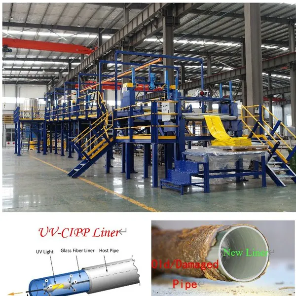
Ready to improve your pipeline quality from the source? Our UV-CIPP liner hose manufacturing machine produces trenchless rehabilitation liners that restore the pressure integrity of aging host pipes without excavation.
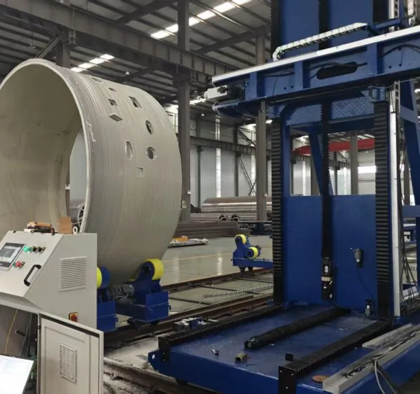
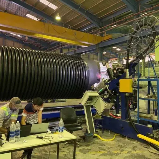
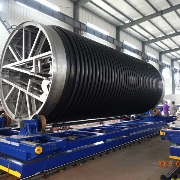
Pressure Testing for Large-Diameter Thermoplastic Pipe
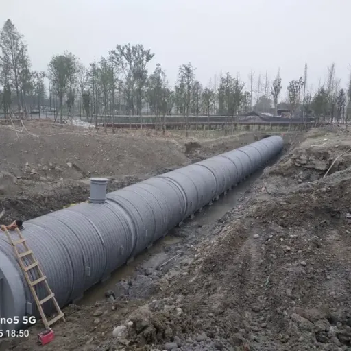
Large-diameter HDPE and PP pipe, including spiral profile pipe used for sewage and drainage, requires special consideration during pressure testing.
Structural Wall Pipe Behavior
Spiral profile pipe has a structured wall with hollow sections that provide ring stiffness. These pipes are designed primarily for gravity and low-pressure applications. Pressure testing must not exceed the pipe's pressure rating, and the test should focus on joint integrity rather than high internal pressure.
Large-Volume Filling
Filling DN2000mm or DN3000mm pipe with water requires significant water volume and time. Plan the test schedule, water source, and disposal method in advance. Some projects use temporary pumps and storage tanks to manage fill and drain cycles.
Thrust Restraint
Internal pressure creates thrust forces at bends, tees, and dead ends. Ensure that thrust blocks, restrained joints, or external anchors are designed for the test pressure, not just operating pressure.
Temperature Stabilization
Large volumes of water change temperature slowly. Allow adequate soak time so the pipe and water reach thermal equilibrium before recording baseline pressure.
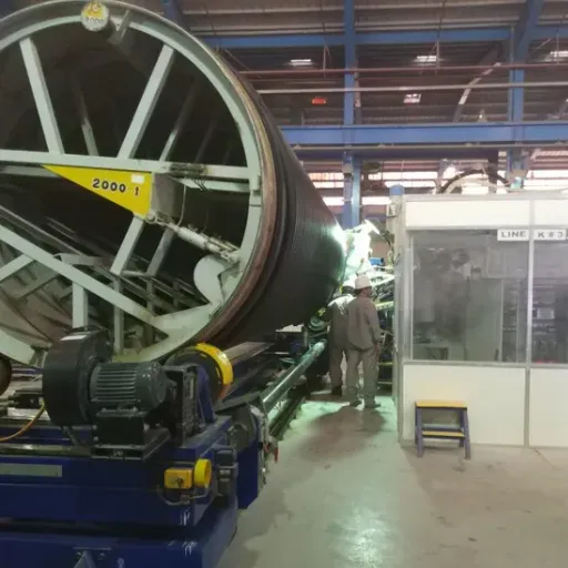
For pipe producers, manufacturing large-diameter pipe with consistent wall thickness and joint geometry makes pressure testing more predictable. Variations in wall thickness create stress concentrations that can produce localized deformation during testing.
Frequently Asked Questions
What is the most common pipe pressure testing method?
Hydrostatic testing is the most common method because water is safe, readily available, and nearly incompressible. It is the standard for water mains, force mains, and most industrial pressure piping.
How long should a pipe pressure test last?
Hold times vary by standard and pipe diameter. Common durations range from 1 hour for small-diameter lines to 24 hours for large municipal pipelines. Always follow the project specification or applicable standard.
Can you pressure test HDPE pipe with air?
Pneumatic testing of HDPE pipe is possible but requires strict safety precautions. Many standards limit pneumatic test pressure and require barriers or restricted access. Hydrostatic testing is generally preferred for HDPE.
What pressure should a pipe pressure test use?
Test pressure is typically 1.25 to 1.5 times the design or operating pressure for hydrostatic tests, and 1.1 times design pressure for pneumatic tests. Confirm the exact multiplier in the governing standard.
What causes pressure loss during a hydrostatic test?
Pressure loss can result from leaks, trapped air, temperature changes, pipe expansion, or absorption of water into the pipe material. Proper preparation and temperature correction help distinguish real leaks from false indications.
Do gravity sewer lines need pressure testing?
Gravity sewer lines are usually tested for leaks using low-pressure air tests, water exfiltration tests, or vacuum tests rather than high-pressure hydrostatic tests. The goal is to verify joint tightness and prevent infiltration or exfiltration.
Conclusion
Pipe pressure testing is the final verification that a pipeline is ready for service. Whether you use hydrostatic, pneumatic, leak, or vacuum testing, success depends on proper preparation, correct test pressure, adequate hold time, and careful documentation. Mistakes such as trapped air, rapid pressurization, and uncalibrated gauges cause unnecessary failures and delays.
Key takeaways for your next project:
Choose the test method based on pipe material, application, and governing standard.
Prepare the line thoroughly: inspect, clean, vent, calibrate, and isolate.
Pressurize in stages and hold for the required duration.
Correct pressure readings for temperature and elevation effects.
Document everything to demonstrate compliance and support warranties.
For pipe manufacturers and contractors who need reliable large-diameter HDPE, PP, and rehabilitation products, Qingdao Yongke Machinery manufactures spiral profile pipe production lines and CIPP liner equipment at our ISO 9001, ISO 14001, and ISO 45001 certified facility.
Recently Posted
-
HDPE Pipe Standards: A Practical Guide for Engineers and Buyers
June 30, 2026A municipal contractor in Southeast Asia once accepted a shipment of HDPE pipe based only on a supplier's diameter claim. Six Read More
 -
Wastewater Collection System Design, Operation, and Renewal
June 30, 2026In late 2021, a coastal city in Southeast Asia discovered that its oldest wastewater collection system had been losing capacity fo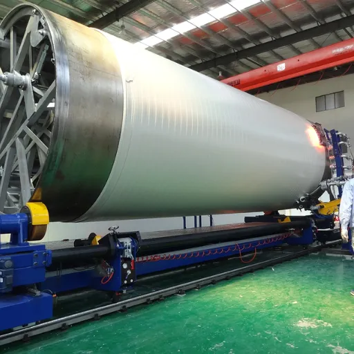 Read More
 -
Wastewater Infrastructure Design, Assessment, and Renewal
June 29, 2026In March 2023, a wastewater treatment plant serving 400,000 residents in Southern Europe suffered a cascade failure. A single inte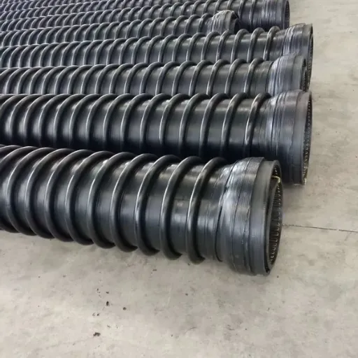 Read More
 -
Combined Sewer System Design, Operation, and Rehabilitation
June 29, 2026In August 2021, a single storm dropped 175mm of rain on a midwestern U.S. city in less than 36 hours. The city's aging combine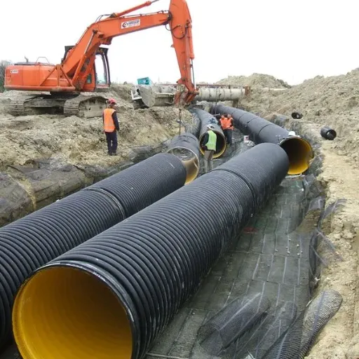 Read More

Contact Us
Recommended Products
-
 CIPP Glass Fibre Liner MachineNegotiableMOQ: 1 Set
 -
HDPE Helically Wound Tank MachineUS$ 10MOQ: 1 Set
-
CIPP Glass Liner MachineNegotiableMOQ: 1 Set
-
CIPP Felt Liner Manufacturing MachineNegotiableMOQ: 1 Set
-
Large Diameter HDPE Sea Intake Outfall Structured Wall Pipe Making MachineNegotiableMOQ: 1 Set
-
UV-CIPP Glass Fibre Liner Manufacturing MachineUS$ 1000 - 110000MOQ: 10 Meters
-
HDPE Pipe Extrusion Machine / PE Pipe Production Line With High OutputNegotiableMOQ: 1 Set
-
UV-CIPP Glass Fiber Liner Hose Production LineUS$ 1000 - 110000MOQ: 1 Set
-
HDPE Spiral Structure Wall Pipe MachineNegotiableMOQ: 1 Set
-
HDPE Spiral Pipe MachineNegotiableMOQ: 1 Set
-
HDPE Spiral Tank MachineNegotiableMOQ: 1 Set
-
Krah Pipe MachineNegotiableMOQ: 1 Set
-
Plastic HDPE PVC PPR Pipe Extrusion Making Machine Extrusion LineNegotiableMOQ: 1 Set
-
PVC Pipe Extrusion Production Line for Electrical Conduit and Water Supply PipesNegotiableMOQ: 1 Set
-
Hot Sell Single Wall Corrugated Pipe Extrusion Line With Competitive PriceNegotiableMOQ: 1 Set
-
HDPE Krah Profild Pipe MachineUS$ 10000MOQ: 1 Set
-
Plastic Tank CNC Holes Boring MachineUS$ 10000MOQ: 1 Set
-
Double Wall Corrugated Pipe Extrusion LineNegotiableMOQ: 1 Set
-
Single Wall Corrugated Pipe Extrusion LineNegotiableMOQ: 1 Set
-
Inversion CIPP Liner Tube Manufacturing MachineNegotiableMOQ: 1 Set