The CIPP Lining Process: A Step-by-Step Guide for Contractors and Engineers
The CIPP lining process transforms a flexible resin-impregnated tube into a rigid structural pipe inside an existing damaged host pipe, typically in 1-12 hours depending on the curing method. It follows a precise sequence: CCTV inspection and cleaning, liner preparation and resin impregnation, installation by inversion or pull-in-place, curing via UV light or hot water/steam, and final quality verification.
For municipal contractors, rehabilitation specialists, and project engineers, mastering each stage of the CIPP lining process ensures consistent quality, avoids costly callbacks, and maximizes the 50-year design life of the rehabilitated pipe. At Qingdao Yongke Machinery, we manufacture the UV-CIPP liner hose manufacturing machines and inversion CIPP liner production equipment that produce the liners used in these field installations worldwide.
Key Takeaways
Every CIPP project requires five core stages: inspection/cleaning, liner preparation, installation, curing, and quality verification.
UV-CIPP cures in 1-3 hours with a robotic light train; inversion CIPP cures in 4-12 hours using circulated hot water or steam.
Proper CCTV inspection and host pipe cleaning determine liner success more than any other pre-installation step.
Resin content must reach 35-45% by weight, and curing parameters must follow resin manufacturer specifications to achieve ASTM F1216 structural properties.
Post-installation CCTV inspection and Barcol hardness testing verify that the liner has cured to full design strength before service restoration.
Stage 1: Pre-Installation Inspection and Cleaning
Successful CIPP lining begins long before the liner enters the pipe. Contractors who rush inspection or skip cleaning steps create conditions for wrinkles, voids, and premature liner failure.
CCTV Camera Inspection
Every project starts with a closed-circuit television (CCTV) camera survey of the host pipe. The inspection documents:
Crack patterns, fractures, and structural defects
Joint separation and offset conditions
Root intrusion locations and severity
Internal diameter variations and sediment deposits
Lateral connection positions and invert conditions
Active infiltration points
The inspection data determines liner design parameters: diameter, length, thickness, resin type, and whether any pre-repair work is needed. For structural liners, engineers calculate required thickness based on pipe diameter, burial depth, groundwater level, and traffic loading per ASTM F1216 or EN ISO 11296 design methods.
In October 2024, a rehabilitation crew in Texas inspected a 300-meter DN600 sewer segment and found a 12-meter section with severe ovality (18% deformation). Rather than installing a standard liner, they first rehabilitated the deformed section with a spot repair, then proceeded with full sectional lining. This pre-emptive assessment prevented a liner that would have bridged across the deformation and created a long-term weak point.
High-Pressure Cleaning
After inspection, high-pressure water jetting cleans the pipe interior to provide a smooth surface for liner contact. Typical cleaning parameters include:
Pressure: 150-250 bar (2,200-3,600 psi) for routine grease and debris removal
Flow rate: 100-300 liters per minute depending on pipe diameter
Nozzle selection: Rotating chain cutters for roots, penetrating nozzles for hard deposits, standard jetting nozzles for soft debris
Mechanical cutting tools may be needed for severe calcium deposits, protruding lateral connections, or encrusted flow lines. The host pipe must present a relatively smooth interior surface. Liners installed over debris or deposits create voids behind the liner that compromise structural bonding and create infiltration paths.
Pre-Installation Assessment
Before proceeding, contractors verify:
Pipe stability: No active collapse, major voids outside the pipe wall, or significant groundwater inflow that could displace uncured resin
Access points: Manholes or cleanouts positioned to allow liner insertion and curing equipment setup
Bypass requirements: Flow must be diverted around the installation segment during the lining operation
Weather conditions: For inversion CIPP, ambient temperature affects curing time; for UV-CIPP, rain entering the pipe during installation is the primary concern
Stage 2: Liner Preparation and Resin Impregnation
The liner tube must be manufactured to precise dimensions and saturated with thermosetting resin before installation. This stage differs significantly between UV-CIPP and inversion CIPP systems.
Inversion CIPP: On-Site Wet-Out
For inversion liners, resin impregnation typically occurs at the job site in a controlled wet-out facility. The process follows these steps:
Resin mixing: Technicians mix resin (polyester, epoxy, or vinyl ester) with catalyst and accelerator according to manufacturer ratios. Ambient temperature determines catalyst dosage, hot weather requires less catalyst to prevent premature curing; cold weather requires more to ensure adequate cure.
Tube saturation: The liner tube unrolls onto a wet-out table while resin is poured and spread across the felt. Rollers or vacuum systems work resin through the fabric to achieve uniform saturation.
Resin content verification: Technicians measure resin content by weighing samples before and after impregnation. Target resin content is 35-45% by weight of the total composite. Too little resin produces a weak liner; too much resin creates exotherm problems during curing and wastes material.
Quality sampling: Laboratory samples are cut from the impregnated liner for flexural testing and resin content verification. These samples cure alongside the installed liner and provide post-installation proof of material properties.
Preparation for inversion: The impregnated liner is rolled or folded into the inversion configuration, with the coated side positioned to become the exterior surface when inverted into the host pipe.
The entire wet-out process must be completed within the resin's pot life, typically 2-4 hours depending on temperature and formulation. This time pressure makes preparation and organization critical on inversion CIPP projects.
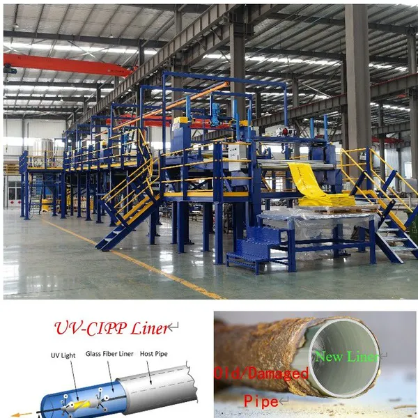
UV-CIPP: Factory Pre-Impregnation
UV-CIPP liners arrive at the job site pre-impregnated and sealed in light-protective packaging. Manufacturers produce these liners under controlled factory conditions:
Tube fabrication: Needle-punched polyester felt or woven fiberglass is cut, sewn, or welded into tubes matching specified diameters and lengths.
Vacuum impregnation: The tube enters a vacuum chamber where air is removed before resin is introduced. Vacuum ensures complete saturation without air voids.
UV-transparent film application: An inner transparent film is bonded to the liner, allowing UV light penetration during curing while containing the resin and creating a smooth internal surface.
Calibration and packaging: The liner passes over calibration mandrels to verify diameter, then is rolled and packaged in opaque wrapping with handling instructions.
Because UV-CIPP liners ship pre-impregnated, contractors eliminate on-site wet-out time and weather variables. The 6-12 month shelf life provides inventory flexibility that inversion liners cannot match.
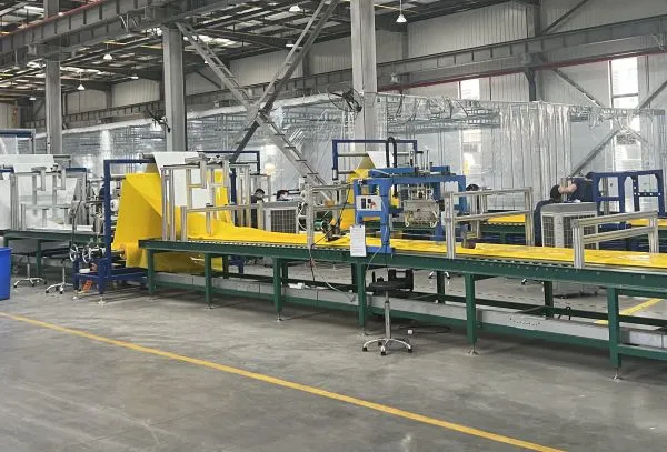
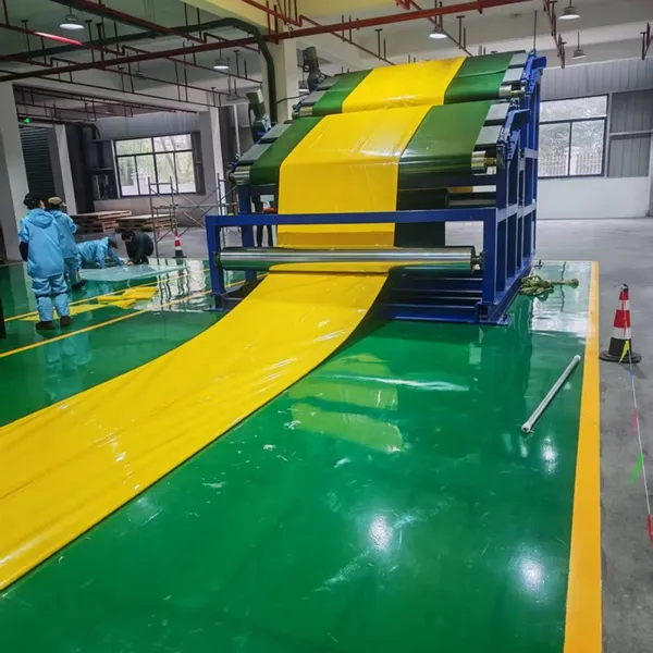
At Qingdao Yongke Machinery, our UV-CIPP liner hose manufacturing machine produces pre-impregnated liners with precise resin content and uniform thickness. For manufacturers entering the trenchless market, UV-CIPP production offers a controlled manufacturing environment that produces more consistent quality than field wet-out operations.
Stage 3: Liner Installation
Installation places the prepared liner inside the host pipe and expands it against the pipe wall. Three primary methods exist: inversion, pull-in-place, and UV-CIPP pull-in.
Inversion Installation
Inversion uses water or air pressure to turn the liner inside-out as it advances through the host pipe:
Setup: The inversion unit, typically a scaffold or truck-mounted system, positions at the upstream manhole. The liner connects to an inversion cone or collar.
Inversion: Water or air pressure pushes against the sealed end of the liner, turning it inside-out as it progresses downstream. The coated exterior surface becomes the inner surface of the finished liner, providing a smooth, corrosion-resistant pipe interior.
Expansion: Pressure holds the inflated liner firmly against the host pipe wall during curing. Pressure typically ranges from 0.3-1.0 bar (4-15 psi) above hydrostatic pressure, depending on pipe diameter and depth.
Termination: The liner terminates at the downstream manhole, where excess material is cut and secured.
Inversion accommodates pipes from DN100 to DN3000+. Water inversion provides better cooling control during hot-water curing; air inversion reduces water disposal requirements and works better in freezing conditions.
UV-CIPP Pull-In or Inversion
UV-CIPP liners may be installed by inversion (using air pressure) or by pulling the liner into position:
Pull-in installation:
A winch cable pulls the pre-impregnated liner through the host pipe from downstream to upstream
An inflation bladder or air pressure expands the liner against the pipe wall
A temporary end seal contains air pressure during curing
Inversion installation:
Air pressure inverts the UV liner through the host pipe similar to inversion CIPP
The inner transparent film allows UV light penetration after inversion
UV-CIPP installation typically serves DN150-DN1200 pipes. For larger diameters, UV light penetration becomes inconsistent, making inversion CIPP the preferred method.
Pull-in-Place for Spot Repairs
Pull-in-Place (PIP) methods install short liner sections for localized defects:
A short liner section, typically 1-3 meters, is pulled to the repair location
An inflatable packer expands the liner against the pipe wall
Curing uses ambient temperature, heat, or UV light depending on the system
After curing, the packer deflates and is removed
PIP dominates the point repair market where full sectional lining is unnecessary or cost-prohibitive.
Stage 4: Curing the Resin
Curing transforms the flexible resin-impregnated liner into a rigid structural pipe. The curing method determines installation time, equipment requirements, and quality control approach.
UV-CIPP Curing: 1-3 Hours
UV curing uses a robotic light train that travels through the inflated liner:
Light train setup: The UV light train, consisting of UV lamps mounted on a cable-driven carriage, enters the liner through an access point.
Progressive curing: The train moves at a controlled speed (typically 0.5-2.0 meters per minute) while UV lamps emit light at wavelengths that initiate resin polymerization. Curing progresses from the entry point outward.
Parameter control: Operators monitor UV intensity, travel speed, and air pressure throughout curing. UV-CIPP systems include sensors that verify cure completion in real time.
Completion: After the light train completes its pass, the liner is structurally cured. Cool-down period is minimal compared to thermal curing.
UV curing completes in 1-3 hours regardless of pipe length because the light train cures progressively as it moves. This speed minimizes traffic control duration and crew time, making UV-CIPP attractive for urban installations where street closure costs accumulate rapidly.
Inversion CIPP Curing: 4-12 Hours
Inversion liners cure through circulated hot water or steam:
Hot water curing:
A boiler truck heats water to 80-99 degrees Celsius (176-210 degrees Fahrenheit)
Heated water circulates through the inflated liner in a closed loop
Temperature sensors monitor the curing front as it progresses through the liner
Cure completion is verified when the entire liner maintains target temperature for the manufacturer's specified duration
Steam curing:
A steam generator produces low-pressure steam
Steam circulates through the liner, transferring heat through condensation
Steam curing typically achieves faster heat-up than hot water but requires more precise pressure control
Curing time depends on liner thickness, pipe diameter, host pipe temperature, and groundwater conditions. A DN800mm liner with 8mm wall thickness may require 6-8 hours of hot water curing, while a DN300mm liner with 4mm thickness may cure in 3-4 hours.
The exothermic reaction of resin curing generates additional heat. For thick liners, this exotherm must be managed to prevent thermal runaway that could damage the liner material.
Curing Quality Control
Regardless of curing method, contractors monitor:
Temperature: Must reach and maintain manufacturer-specified cure temperature
Pressure: Must hold liner against host pipe wall throughout curing
Time: Must meet minimum cure duration for the liner thickness and resin system
Environmental conditions: Groundwater infiltration or ambient temperature changes can affect cure
Incomplete curing produces a liner with inadequate flexural strength and Barcol hardness, compromising structural performance. Rushing curing to meet a schedule is a leading cause of CIPP liner failure.
Stage 5: Post-Installation Inspection and Service Restoration
After curing, technicians verify liner quality before returning the pipe to service.
CCTV Post-Inspection
A post-installation CCTV survey verifies:
Liner placement without wrinkles, folds, or bridging
Proper termination at access points with adequate overlap
Absence of voids or delamination
Correct internal diameter after installation
Lateral connection locations identified for reopening
High-resolution cameras with laser profiling measure the finished internal diameter and detect any ovality or deformation. This documentation becomes part of the project quality record.
Service Lateral Reopening
Service lateral connections must be reopened through the cured liner to restore house connections and branch lines:
Location: CCTV inspection identifies lateral positions; some systems use sonar or electromagnetic sensors for precise location.
Cutting: Robotic cutters with high-speed milling heads mill precise openings through the liner without damaging the host pipe.
Sealing: Some installations apply internal seals around lateral connections to prevent infiltration at the interface.
Lateral reopening requires skilled operators. Poor cutting technique can damage the liner or leave rough edges that catch debris and cause blockages.
Quality Testing
Post-installation testing verifies that the liner meets design specifications:
Barcol hardness: A handheld durometer measures surface hardness at multiple points. Values below manufacturer minimums indicate incomplete cure.
Flexural properties: Laboratory testing of cured samples cut from the liner verifies flexural strength and modulus per ASTM D790.
Leakage testing: Air or water exfiltration tests verify that the rehabilitated pipe is watertight.
Thickness verification: Ultrasonic gauges or core samples verify that installed thickness matches design calculations.
Service Restoration
After quality verification passes, contractors:
Remove bypass pumping equipment and restore normal flow
Clean manholes and remove construction debris
Replace manhole covers and restore surface features
Document the installation with photos, CCTV recordings, and test reports
Submit as-built documentation to the project engineer or owner
For municipal sewer rehabilitation, flow restoration typically occurs within hours after UV-CIPP installation or the following day after inversion CIPP, depending on project logistics.
CIPP Lining Process Comparison by Technology
| Stage | UV-CIPP | Inversion CIPP (Hot Water) | Pull-in-Place |
|---|---|---|---|
| Pre-installation inspection | CCTV + cleaning required | CCTV + cleaning required | CCTV + cleaning required |
| Resin impregnation | Factory pre-impregnated | On-site wet-out | On-site or pre-impregnated |
| Installation method | Pull-in or air inversion | Water/air inversion | Pull-in with packer |
| Curing method | UV light train | Hot water/steam circulation | Ambient, heat, or UV |
| Curing time | 1-3 hours | 4-12 hours | 1-24 hours (system dependent) |
| Shelf life | 6-12 months | 2-4 weeks (refrigerated) | Varies |
| Diameter range | DN150-DN1200 | DN100-DN3000+ | DN100-DN600 |
| Equipment at site | UV light train, compressor | Boiler truck, water handling | Packer, curing equipment |
| Weather sensitivity | Low | High (affects cure time) | Moderate |
This comparison helps contractors and project owners select the appropriate technology for specific project conditions. Urban projects with tight traffic control windows often favor UV-CIPP for its speed, while large-diameter rural projects may favor inversion CIPP for its diameter range and lower equipment costs.
Equipment Requirements for CIPP Liner Production
Contractors who rely on purchased liners from third-party suppliers face lead times, shipping costs, and limited control over quality. Manufacturers who produce their own liners gain supply chain control and margin capture.
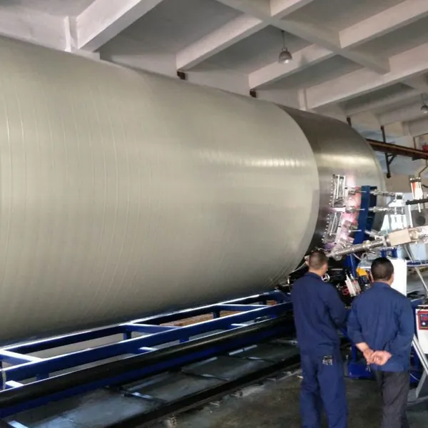
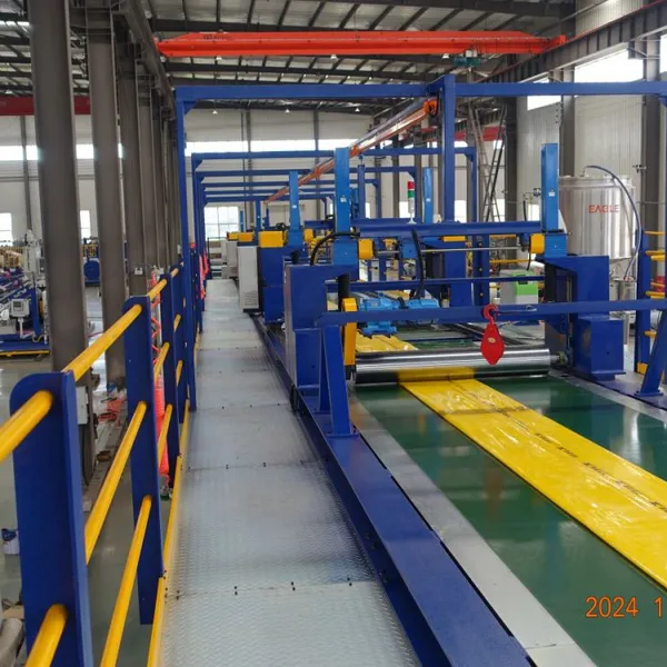
UV-CIPP Liner Manufacturing Equipment
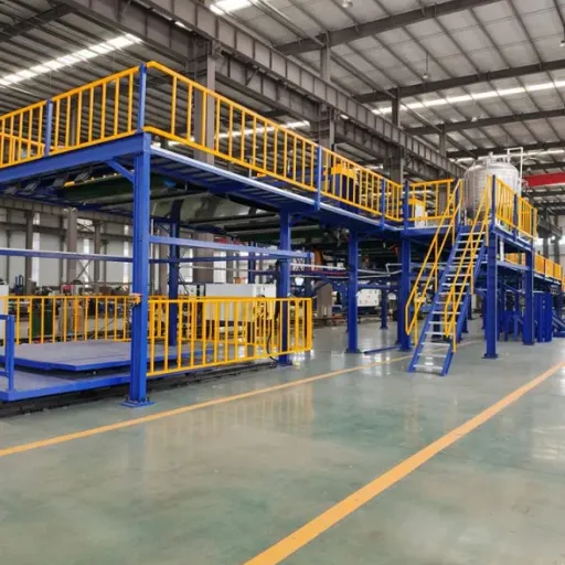
A complete UV-CIPP liner production line includes:
Felt tube production: High-speed needle punching or weaving machines, tube sewing/welding stations with diameter calibration
Vacuum impregnation system: Removes air and ensures complete resin saturation with precise metering
UV-transparent film line: Extrusion or lamination equipment applying the inner cure film at 0.1-0.3mm thickness
Calibration and winding: Mandrel systems for diameter verification, automated rolling and packaging
Quality testing laboratory: Equipment for resin content, flexural properties, and Barcol hardness testing
Inversion Liner Manufacturing Equipment
Inversion liner production requires:
Tube fabrication equipment: Felt production or tube forming and sewing stations
Wet-out facility: Temperature and humidity controlled environment for resin impregnation
Calibration tables: Ensure uniform thickness across the liner circumference
Outer coating system: Polyethylene or polyurethane coating for installation lubricity
Packaging equipment: Folding and rolling systems designed for inversion installation
Interested in producing CIPP liners in-house? At Qingdao Yongke Machinery, we engineer both UV-CIPP liner hose manufacturing machines and inversion CIPP liner hose machines for manufacturers entering the trenchless rehabilitation market. Contact our engineering team for production line configuration, capacity calculations, and equipment quotations.
Common CIPP Installation Mistakes and How to Avoid Them
Even experienced contractors encounter problems. Understanding common failures helps teams prevent costly rework.
Inadequate Cleaning: Residual grease, roots, or calcium deposits prevent the liner from bonding to the host pipe. Always verify cleaning quality with post-cleaning CCTV before proceeding.
Incorrect Resin Mixing: Catalyst ratios that are off by even small percentages can cause incomplete cure or premature gelation. Use calibrated metering equipment and follow manufacturer charts for ambient temperature conditions.
Pressure Loss During Curing: Groundwater infiltration, equipment failure, or seal leaks can cause the liner to deflate before curing completes. Install redundant pressure monitoring and have backup equipment on site.
Rushing the Cure: Every resin system has a minimum cure time at specified temperature. Contractors who remove curing equipment early to meet schedules risk installing liners with inadequate structural properties.
Poor Lateral Cutting: Rough or oversized lateral openings create infiltration points and debris catchment areas. Use sharp, properly sized cutting heads and verify reopening quality with CCTV.
Conclusion
The CIPP lining process transforms deteriorated underground pipes into structurally sound, corrosion-resistant infrastructure without excavation. Each stage, from pre-installation inspection through curing and quality verification, requires technical precision, proper equipment, and adherence to material specifications.
For contractors, mastering the CIPP lining process means understanding how UV curing, hot water curing, and pull-in-place methods each suit different project conditions. For manufacturers, producing high-quality liners that perform consistently in the field builds reputation and repeat business in the growing trenchless rehabilitation market.
The global demand for no-dig pipe repair continues to expand as municipalities face aging infrastructure and budget constraints. Contractors and manufacturers who invest in process knowledge and quality equipment position themselves to capture this growth.
At Qingdao Yongke Machinery, a pipe machine manufacturer since 2010, we design and build UV-CIPP liner hose manufacturing machines and inversion CIPP liner production lines at our ISO 9001 certified facility in Qingdao, China. Our equipment produces liners that contractors install daily on municipal sewer, industrial pipeline, and drainage rehabilitation projects worldwide.
For technical specifications, production capacity planning, or equipment quotations, contact Mr. Zhou Maozhen at machinery@eaglegroup.cn or via WhatsApp at +86-13583232887.
Recently Posted
-
Cured In Place Pipe (CIPP): A Complete Guide to Trenchless Rehabilitation
June 17, 2026A cured in place pipe (CIPP) is a trenchless rehabilitation method that creates a new structural pipe inside an existing damaged s Read More
 -
HDPE Pipe Recycling: How to Turn Scrap Into Structural Pipe Products
June 17, 2026HDPE pipe recycling is the process of collecting, sorting, cleaning, and reprocessing high-density polyethylene pipe scrap into re Read More
 -
Stormwater Management Systems: A Complete Guide for Municipal and Industrial Projects
June 17, 2026A stormwater management system controls the quantity and quality of runoff from rainfall and snowmelt, protecting properties, road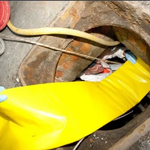 Read More
 -
HDPE Pipe Installation: A Complete Guide for Sewer and Water Projects
June 17, 2026HDPE pipe installation is the process of placing, joining, and commissioning high-density polyethylene pipe for water, sewer, gas, Read More

Contact Us
Recommended Products
-
 CIPP Glass Fibre Liner MachineNegotiableMOQ: 1 Set
 -
HDPE Helically Wound Tank MachineUS$ 10MOQ: 1 Set
-
CIPP Glass Liner MachineNegotiableMOQ: 1 Set
-
CIPP Felt Liner Manufacturing MachineNegotiableMOQ: 1 Set
-
Large Diameter HDPE Sea Intake Outfall Structured Wall Pipe Making MachineNegotiableMOQ: 1 Set
-
UV-CIPP Glass Fibre Liner Manufacturing MachineUS$ 1000 - 110000MOQ: 10 Meters
-
HDPE Pipe Extrusion Machine / PE Pipe Production Line With High OutputNegotiableMOQ: 1 Set
-
UV-CIPP Glass Fiber Liner Hose Production LineUS$ 1000 - 110000MOQ: 1 Set
-
HDPE Spiral Structure Wall Pipe MachineNegotiableMOQ: 1 Set
-
HDPE Spiral Pipe MachineNegotiableMOQ: 1 Set
-
HDPE Spiral Tank MachineNegotiableMOQ: 1 Set
-
Krah Pipe MachineNegotiableMOQ: 1 Set
-
Plastic HDPE PVC PPR Pipe Extrusion Making Machine Extrusion LineNegotiableMOQ: 1 Set
-
PVC Pipe Extrusion Production Line for Electrical Conduit and Water Supply PipesNegotiableMOQ: 1 Set
-
Hot Sell Single Wall Corrugated Pipe Extrusion Line With Competitive PriceNegotiableMOQ: 1 Set
-
HDPE Krah Profild Pipe MachineUS$ 10000MOQ: 1 Set
-
Plastic Tank CNC Holes Boring MachineUS$ 10000MOQ: 1 Set
-
Double Wall Corrugated Pipe Extrusion LineNegotiableMOQ: 1 Set
-
Single Wall Corrugated Pipe Extrusion LineNegotiableMOQ: 1 Set
-
Inversion CIPP Liner Tube Manufacturing MachineNegotiableMOQ: 1 Set