Retention Pond Drainage: Design, Outlets, and Maintenance
In August 2022, a summer storm parked over the new Meridian Business Park near Dallas for six hours. The retention pond had been built to code, but its outlet pipe was partially blocked by sediment and debris. Water rose faster than the design release rate allowed, and the pond overtopped into the parking lot. Three vehicles were damaged, and the developer faced $90,000 in emergency repairs before the site could reopen.
If you design, build, or maintain stormwater infrastructure, retention pond drainage isn't just a detail. It's the difference between a pond that protects downstream property and one that becomes a liability. The right outfall, the right pipe, and the right maintenance plan keep the system working across decades of storms.
This guide explains how retention pond drainage works, how to size outlets and emergency spillways, how to select pipe materials, and how to avoid the failures that catch experienced engineers off guard. The guidance reflects standard municipal stormwater practice and Yongke Machinery's 16+ years of supporting large-diameter pipe production for drainage projects worldwide.
What Is a Retention Pond and How Does Drainage Work?
A retention pond, also called a wet detention pond, is a permanent pool of water designed to treat and slowly release stormwater runoff. Unlike a dry detention basin, which empties after a storm, a retention pond holds a permanent water surface. The stored volume allows sediment and pollutants to settle before the treated water discharges through an outlet structure.
Retention pond drainage serves three functions at once:
Flow control: It releases water slowly to limit downstream peak flows.
Water quality treatment: It provides settling time for sediment, nutrients, and debris.
Flood storage: It temporarily stores excess runoff above the normal pool during large storms.
The drainage system typically includes a principal outlet, an emergency spillway, and a low-flow orifice. Each component must be sized for the design storm, the catchment area, and the receiving channel. If any one of these elements is undersized or poorly maintained, the pond can fail during an event smaller than the design storm.
Engineering Note: Always verify the required permanent pool elevation, water quality volume, and flood control volume before sizing the outlet structure. Local stormwater ordinances often specify detention times between 24 and 72 hours.
Key Design Factors for Retention Pond Drainage
Before sizing pipes or drawing details, engineers must collect site and regulatory inputs. Each one changes the drainage design.
Catchment Area and Runoff Volume
The upstream drainage area defines how much runoff enters the pond. Larger impervious areas produce more runoff in less time. Engineers estimate the runoff hydrograph using the Rational Method for small catchments or hydrologic models such as HEC-HMS or SWMM for larger ones.
Design Storm Return Period
Most jurisdictions require retention ponds to detain or retain runoff from specific design storms. Common standards include the 2-year, 10-year, 25-year, and 100-year events. The pond must safely pass the 100-year storm through the emergency spillway without overtopping the embankment.
Permitted Release Rate
The maximum allowable discharge is usually set by downstream capacity. A common rule limits the post-development peak flow to the pre-development peak flow for the same design storm. The outlet structure must throttle the release to meet this limit.
Detention Time
Water quality treatment depends on how long runoff remains in the pond. A longer detention time improves settling but requires a larger permanent pool or smaller outlet orifice. Typical water quality detention times range from 24 to 72 hours.
Pond Geometry and Side Slopes
Pond shape affects flow paths, mixing, and sediment distribution. Side slopes are usually 3:1 or flatter for safety and maintenance access. A length-to-width ratio of at least 3:1 improves settling efficiency by reducing short-circuiting.
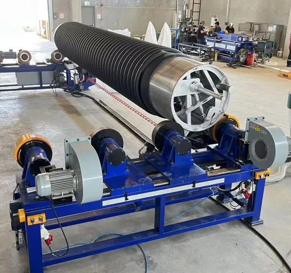
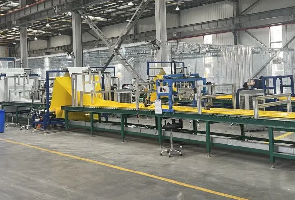
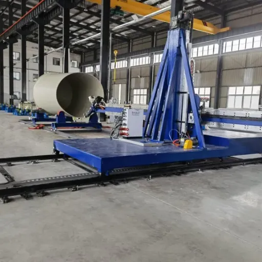
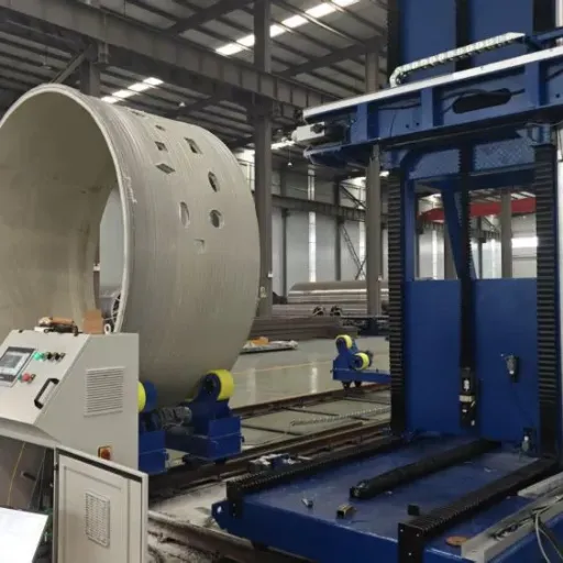
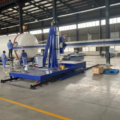
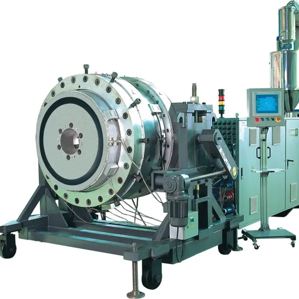
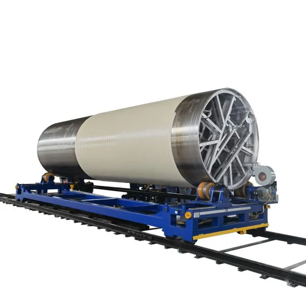
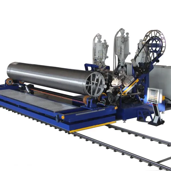
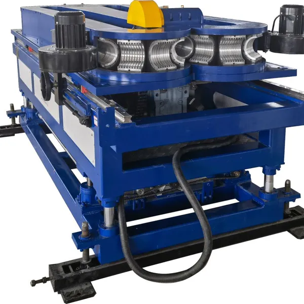
Need large-diameter pipe for a retention pond outfall? Explore Yongke's DN300–DN5000mm HDPE/PP spiral profile pipe production line.
Sizing the Principal Outlet and Emergency Spillway
The outlet structure is the heart of retention pond drainage. It controls the release rate across the full range of storm events.
The Riser and Barrel Assembly
A typical principal outlet uses a vertical riser connected to a horizontal barrel. The riser has openings or weirs at different elevations to release water at different rates. The barrel conveys flow through the embankment to the downstream channel.
For small ponds, a single orifice may be enough. For larger ponds, a multi-stage riser with a water quality orifice, a detention weir, and an emergency overflow is standard.
Orifice Flow and Weir Flow
Outlet hydraulics depend on whether water flows through an orifice or over a weir.
For orifice flow:
Q = C × A × √(2gh)
Where:
Q = discharge
C = discharge coefficient
A = orifice area
g = gravitational acceleration
h = head above the orifice centerline
For weir flow:
Q = C × L × h^(3/2)
Where:
L = weir length
h = head above the weir crest
Engineers iterate orifice size, weir length, and barrel diameter until the stage-discharge curve meets the target release rate across all design storms.
Emergency Spillway Design
The emergency spillway provides a safe path for flows that exceed the principal outlet capacity. It is usually a broad-crested weir through undisturbed material or a grass-lined channel. The spillway must pass the 100-year storm without eroding the embankment.
A common design error is treating the spillway as an afterthought. If the principal outlet clogs, the spillway becomes the only outlet. Its capacity must be verified independently, and its invert must be set above the maximum water surface for the design storm handled by the principal outlet.
For detailed guidance on hydraulic design of outlet structures, the Federal Highway Administration Hydraulic Design Series No. 5 provides authoritative methods applicable to detention and retention facilities.
Selecting Pipe Materials for Retention Pond Outfalls
The barrel pipe that passes through the embankment must withstand internal pressure, external soil loads, and fluctuating water levels. Material selection affects hydraulic capacity, service life, and maintenance frequency.
HDPE and PP Spiral Profile Pipe
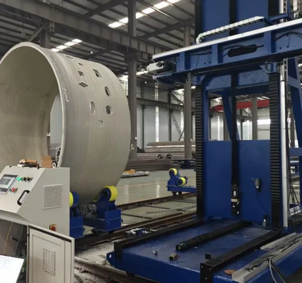
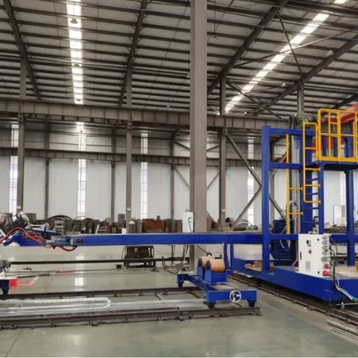
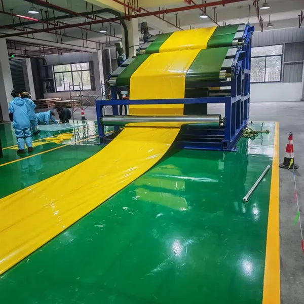
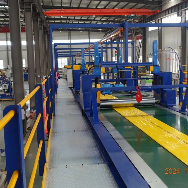
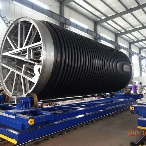
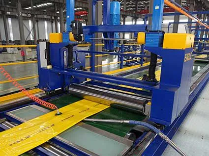
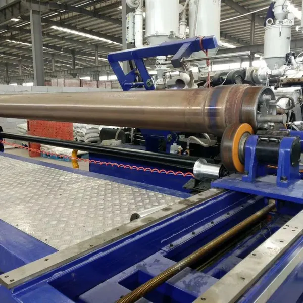
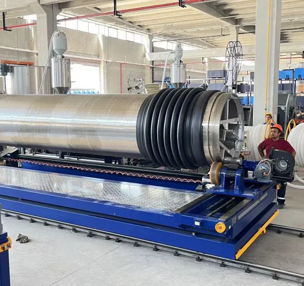
HDPE and PP spiral profile pipe is well suited to retention pond outfalls, especially for diameters above DN600mm. The smooth interior provides a low Manning's n, while the structural wall profile gives ring stiffness for buried applications. It resists corrosion, accepts heat-fused or welded joints, and is available in diameters up to DN5000mm.
For ponds with long outfall lines or large catchments, producing pipe on-site with a spiral profile pipe machine can reduce transportation costs and improve delivery control.
Reinforced Concrete Pipe
Reinforced concrete pipe is stiff and durable. It performs well under high embankment loads and is widely accepted by municipal specifiers. However, it is heavier, more susceptible to corrosion in aggressive soils, and has a higher Manning's n than HDPE.
Corrugated Metal Pipe
Corrugated metal pipe is sometimes used for smaller outfalls and culverts. It is lightweight and easy to install but has higher roughness and lower corrosion resistance than HDPE or concrete.
Material Comparison Table
| Feature | HDPE/PP Spiral Profile | Reinforced Concrete | Corrugated Metal |
|---|---|---|---|
| Manning's n | 0.009–0.012 | ~0.013 | 0.022–0.030 |
| Corrosion resistance | Excellent | Moderate | Low to moderate |
| Typical maximum diameter | DN5000mm+ | DN3600mm common | DN3000mm common |
| Weight | Light | Heavy | Moderate |
| Joint type | Heat-fused / welded | Gasketed | Band-connected |
Mini-Story: When a Clogged Orifice Flooded a Subdivision
In 2018, engineer David Okonkwo designed a retention pond for a residential subdivision outside Lagos. The catchment was 12 hectares, mostly rooftops and paved roads. He specified a multi-stage concrete riser with a 150 mm diameter water quality orifice.
The pond worked well for the first two rainy seasons. By the third year, sediment and vegetation had partially blocked the orifice. A 10-year storm produced a peak inflow that should have passed safely through the outlet.
Instead, the pond level rose above the design water surface and flowed over the emergency spillway. The spillway had not been armored properly, and erosion began to undermine the embankment.
The repair cost the developer $45,000 and required a redesign of the outlet structure with a trash rack, an access manhole, and a larger maintenance envelope. David's lesson: retention pond drainage design is only as good as the maintenance access it allows.
Retention Pond Drainage Maintenance and Common Failures
Retention ponds are exposed to sediment, debris, vegetation, and fluctuating water levels. Without regular maintenance, even a well-designed system will degrade.
Sediment Accumulation
Sediment reduces storage volume and can smother vegetation in the permanent pool. Most jurisdictions require sediment removal when the storage volume drops by 20% to 30%. Regular surveys using sounding poles or bathymetry help track sediment depth.
Outlet Clogging
Orifices, trash racks, and riser openings are prone to clogging from leaves, litter, and vegetation. Trash racks must be sized with openings small enough to block debris but large enough to pass the design flow. Access for cleaning should be designed into every outlet structure.
Vegetation and Embankment Damage
Cattails, reeds, and woody growth can block inlets and outlets. Embankments must be mowed and inspected for animal burrows, erosion, or settlement. Damaged slopes can lead to embankment failure during large storms.
Structural Deterioration
Concrete risers can crack. Metal pipes can corrode. Gasketed joints can leak. Inspection programs should include visual checks after major storms and detailed assessments every few years.
Planning a retention pond or stormwater outfall project? Request a customized quotation for spiral profile pipe matched to your diameter and flow requirements.
Integrating Retention Ponds with Overall Stormwater Strategy
Retention ponds do not work in isolation. They connect to streets, gutters, inlet structures, downstream channels, and treatment systems. Without proper coordination, even a correctly sized pond can receive less flow than expected or discharge more than the downstream channel can carry.
Coordination with Site Grading
Inlets must be located where runoff naturally collects. The pond bottom and permanent pool must be set below the lowest inlet elevation. Poor grading can leave inlets that drain poorly or bypass the pond entirely.
Pretreatment and Forebays
A forebay at the inlet slows incoming flow and traps coarse sediment before it reaches the main pond. This reduces maintenance in the permanent pool and extends the life of the outlet structure.
Downstream Channel Protection
Even a properly sized outlet can release water at velocities that erode the downstream channel. Energy dissipaters, riprap aprons, or level spreaders may be needed at the outfall.
Green Infrastructure Pairing
Permeable pavement, bioswales, and rain gardens can reduce runoff volume before it reaches the pond. In some cases, upstream green infrastructure allows a smaller pond or reduces the required flood control volume. The U.S. Environmental Protection Agency's stormwater management guidance summarizes how these practices fit into a comprehensive drainage strategy.
At Yongke Machinery, we support municipal contractors and pipe producers with HDPE/PP spiral profile pipe production lines from DN300mm to DN5000mm. Whether your project needs retention pond outfalls, detention basin barrels, or stormwater trunk lines, producing pipe locally can improve logistics and delivery control.
Retention Pond Drainage Design Checklist
Use this checklist during design review to catch common oversights before construction begins:
Confirm the required water quality volume, permanent pool elevation, and flood control volume with the local authority.
Size the principal outlet for the full range of design storms, not just the 100-year event.
Verify the emergency spillway passes the 100-year storm without overtopping the embankment.
Provide trash racks and maintenance access at every orifice and riser opening.
Select pipe material based on embankment load, corrosion exposure, and hydraulic capacity.
Protect the downstream channel with riprap, energy dissipaters, or level spreaders.
Plan for sediment removal access, including stable haul roads and dewatering areas.
Coordinate pond grading with site drainage so every inlet actually drains to the pond.
Conclusion
Retention pond drainage is a critical part of stormwater management. The design must balance flow control, water quality treatment, and flood protection across a wide range of storm events. Proper outlet sizing, durable pipe materials, and a realistic maintenance plan determine whether the pond performs as intended over its design life.
Key Takeaways
Retention ponds hold a permanent pool and release treated runoff slowly through a principal outlet.
The outlet structure must be sized for water quality detention, flood control, and emergency overflow.
HDPE and PP spiral profile pipe offers low roughness and large diameter range for outfall applications.
Maintenance access and trash protection are as important as hydraulic calculations.
Regular inspection, sediment removal, and vegetation control prevent costly failures.
If your project involves DN300mm to DN5000mm drainage pipe for retention ponds, detention basins, or stormwater outfalls, Yongke Machinery can help you evaluate production options, material selection, and diameter range. Contact our engineering team to discuss your hydraulic requirements, request a quotation, or schedule a technical consultation.
Recently Posted
-
HDPE Pipe Standards: A Practical Guide for Engineers and Buyers
June 30, 2026A municipal contractor in Southeast Asia once accepted a shipment of HDPE pipe based only on a supplier's diameter claim. Six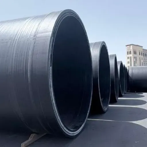 Read More
 -
Wastewater Collection System Design, Operation, and Renewal
June 30, 2026In late 2021, a coastal city in Southeast Asia discovered that its oldest wastewater collection system had been losing capacity fo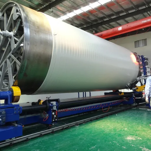 Read More
 -
Wastewater Infrastructure Design, Assessment, and Renewal
June 29, 2026In March 2023, a wastewater treatment plant serving 400,000 residents in Southern Europe suffered a cascade failure. A single inte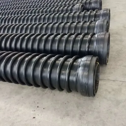 Read More
 -
Combined Sewer System Design, Operation, and Rehabilitation
June 29, 2026In August 2021, a single storm dropped 175mm of rain on a midwestern U.S. city in less than 36 hours. The city's aging combine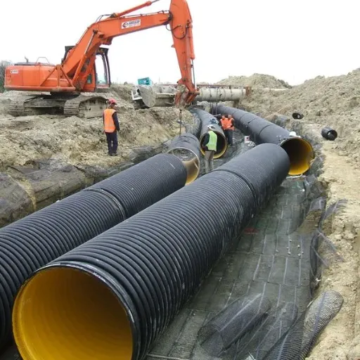 Read More

Contact Us
Recommended Products
-
 CIPP Glass Fibre Liner MachineNegotiableMOQ: 1 Set
 -
HDPE Helically Wound Tank MachineUS$ 10MOQ: 1 Set
-
CIPP Glass Liner MachineNegotiableMOQ: 1 Set
-
CIPP Felt Liner Manufacturing MachineNegotiableMOQ: 1 Set
-
Large Diameter HDPE Sea Intake Outfall Structured Wall Pipe Making MachineNegotiableMOQ: 1 Set
-
UV-CIPP Glass Fibre Liner Manufacturing MachineUS$ 1000 - 110000MOQ: 10 Meters
-
HDPE Pipe Extrusion Machine / PE Pipe Production Line With High OutputNegotiableMOQ: 1 Set
-
UV-CIPP Glass Fiber Liner Hose Production LineUS$ 1000 - 110000MOQ: 1 Set
-
HDPE Spiral Structure Wall Pipe MachineNegotiableMOQ: 1 Set
-
HDPE Spiral Pipe MachineNegotiableMOQ: 1 Set
-
HDPE Spiral Tank MachineNegotiableMOQ: 1 Set
-
Krah Pipe MachineNegotiableMOQ: 1 Set
-
Plastic HDPE PVC PPR Pipe Extrusion Making Machine Extrusion LineNegotiableMOQ: 1 Set
-
PVC Pipe Extrusion Production Line for Electrical Conduit and Water Supply PipesNegotiableMOQ: 1 Set
-
Hot Sell Single Wall Corrugated Pipe Extrusion Line With Competitive PriceNegotiableMOQ: 1 Set
-
HDPE Krah Profild Pipe MachineUS$ 10000MOQ: 1 Set
-
Plastic Tank CNC Holes Boring MachineUS$ 10000MOQ: 1 Set
-
Double Wall Corrugated Pipe Extrusion LineNegotiableMOQ: 1 Set
-
Single Wall Corrugated Pipe Extrusion LineNegotiableMOQ: 1 Set
-
Inversion CIPP Liner Tube Manufacturing MachineNegotiableMOQ: 1 Set